Redefining the construction industry with innovative solutions, cutting-edge technology and sustainable practices
Redefining the construction industry with innovative solutions, cutting-edge technology and sustainable practices
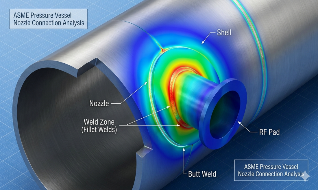
Finite Element Analysis (FEA) of Nozzle V1 is carried out to evaluate stress distribution at the nozzle junction under operating conditions in accordance with ASME Section VIII standards.
Finite Element Analysis (FEA) of Nozzle V1 is carried out as per ASME Section VIII, Division 1 (Edition 2023) to evaluate the stress distribution at the nozzle junction and ensure structural integrity under operating conditions. The primary objective of this analysis is to identify critical stress regions and verify the design against allowable stress limits. The study follows the guidelines of ASME Section VIII, Division 2, Part 5.2 for protection against plastic collapse, and stress comparisons are performed as per ASME Section VIII, Division 2, including Figure 5.1.
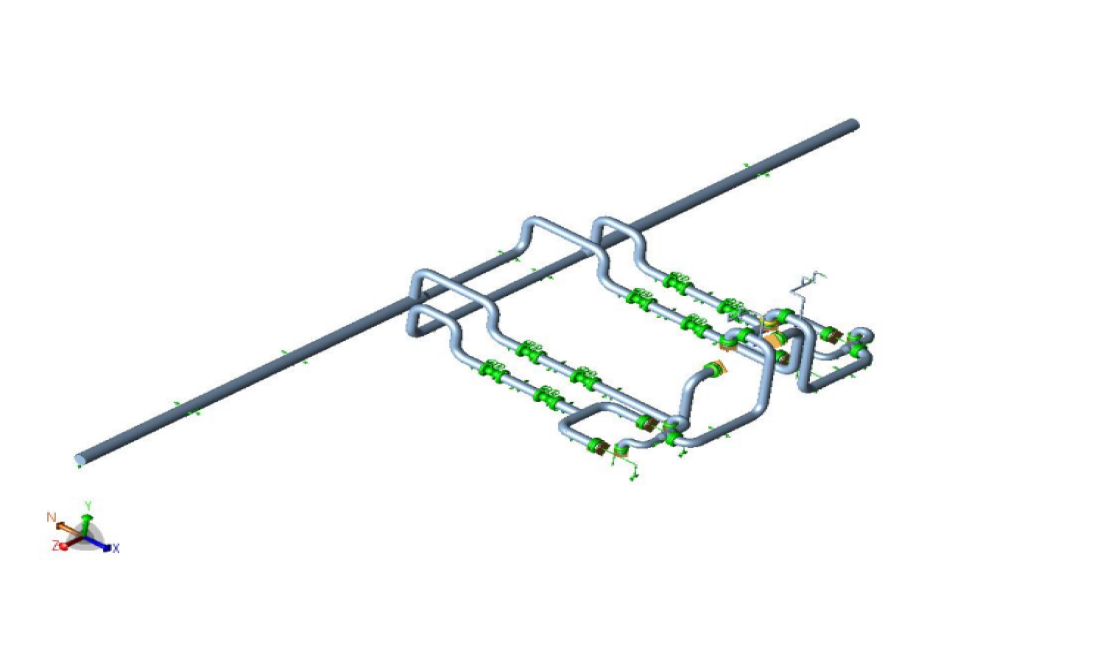
For the purpose of analysis, a detailed three-dimensional model is developed, and the finite element simulation is carried out . The model includes all relevant geometric features such as the nozzle, flange connections, and adjoining components to accurately represent real conditions. A high-quality finite element mesh is generated, with finer mesh applied in the nozzle junction region to capture stress concentration effects accurately.
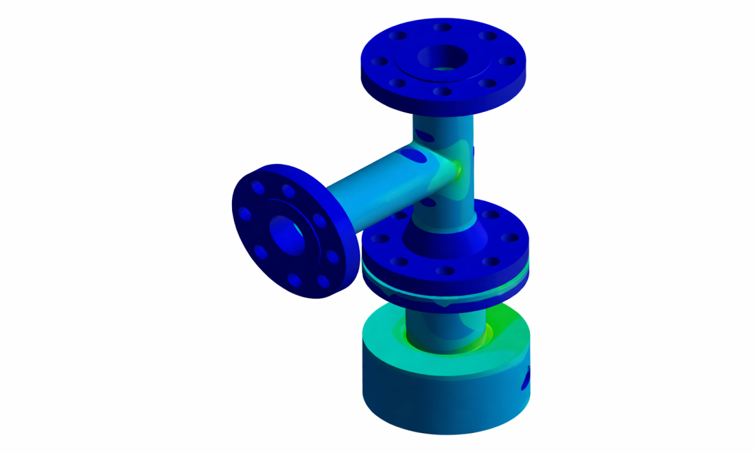
The analysis considers various loading and boundary conditions, including internal pressure, nozzle loads (forces and moments), and appropriate constraints. The results obtained from the simulation show that the maximum equivalent (von Mises) stress occurs near the nozzle junction region, as highlighted in the stress contour plot. These stress values are compared with allowable limits specified by ASME standards to assess the safety and reliability of the design.
Based on the results, the critical stress region is identified at the nozzle junction, and the design is evaluated for structural adequacy under the applied loading conditions. The study includes detailed methodology, meshing strategy, loading conditions, and evaluation of all relevant load cases, providing a comprehensive assessment of the nozzle performance.
The figures show the equivalent (von Mises) stress distribution and mesh model for Nozzle V1, highlighting the maximum stress location at the nozzle junction and refined mesh used for accurate stress evaluation.
© 2025. Made by Webteam . All rights reserved. Aaradhya Design and Build Pvt Ltd.